

Metal Stud Specifications: What to Check First
Start with stud depth, steel thickness, spacing, and the wall’s required height. Common drywall stud depths range from 1-5/8 to 6 inches. Do not rely on a gauge label alone: check the listed design thickness, yield strength, and limiting-height table for the exact stud and wall assembly. Reviewing metal studs specifications carefully helps you confirm that a taller wall, wider stud spacing, or stricter deflection limit won’t call for a deeper or thicker stud than what’s on order.
The drywall and fasteners matter, too. A limiting height based on gypsum board attached to both sides may not apply to a wall with board on only one side. Check the specified screw pattern and choose Grabber fasteners suited to the stud thickness and board.
At Western Wholesale Supply, our team works with contractors on steel framing, drywall, and related products. We’ll walk through the metal studs specifications that help you order the right materials and avoid changes on site.
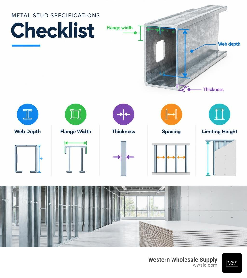
Understanding Metal Studs Specifications and Nomenclature
Cold-formed steel framing has transformed modern commercial and residential construction. Unlike traditional timber, steel studs arrive straight, stay straight, and will never rot, warp, twist, or bow over time. When exploring prefabricated framing advantages, understanding the exact geometry of cold-formed steel components ensures your layout stays plumb and structurally sound.
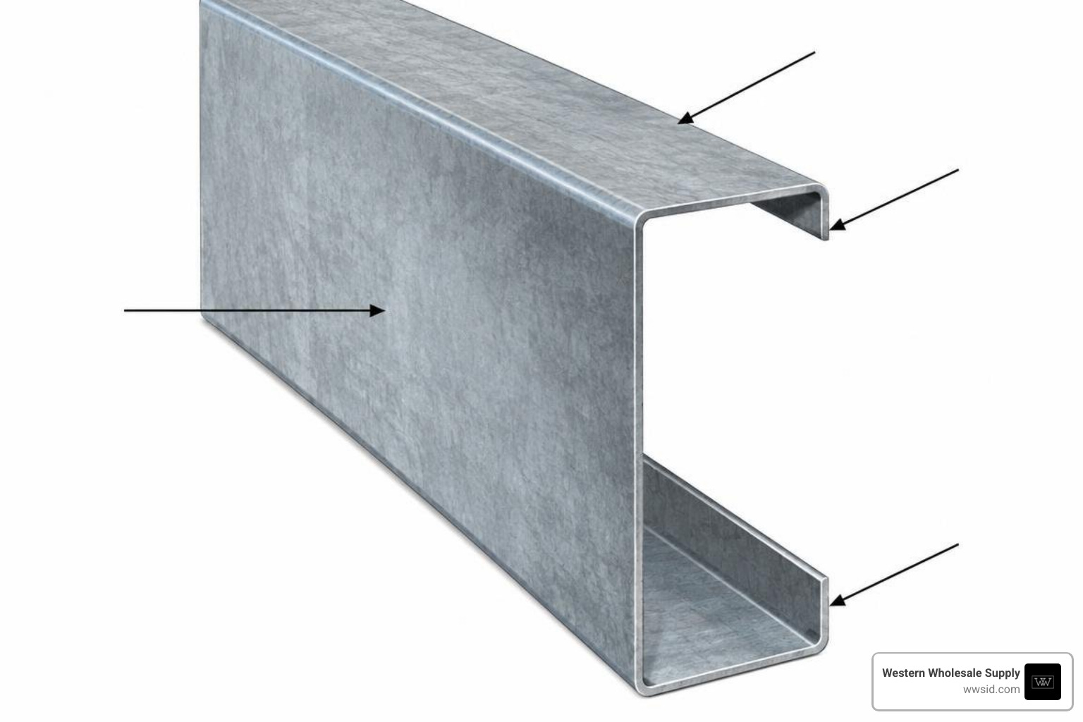
Every standard cold-formed steel C-stud consists of three primary elements:
- Web: The wide flat back of the stud that defines overall wall depth.
- Flanges: The perpendicular legs extending outward from the web to provide a fastening surface.
- Return Lips: The small inward-turned stiffening edges on each flange that resist local buckling under axial and lateral loads.
Decoding Member Codes and Standard Sizes
The cold-formed steel industry uses a standardized alphanumeric designation system established by the American Iron and Steel Institute (AISI). This four-part callout describes every parameter you need to verify:
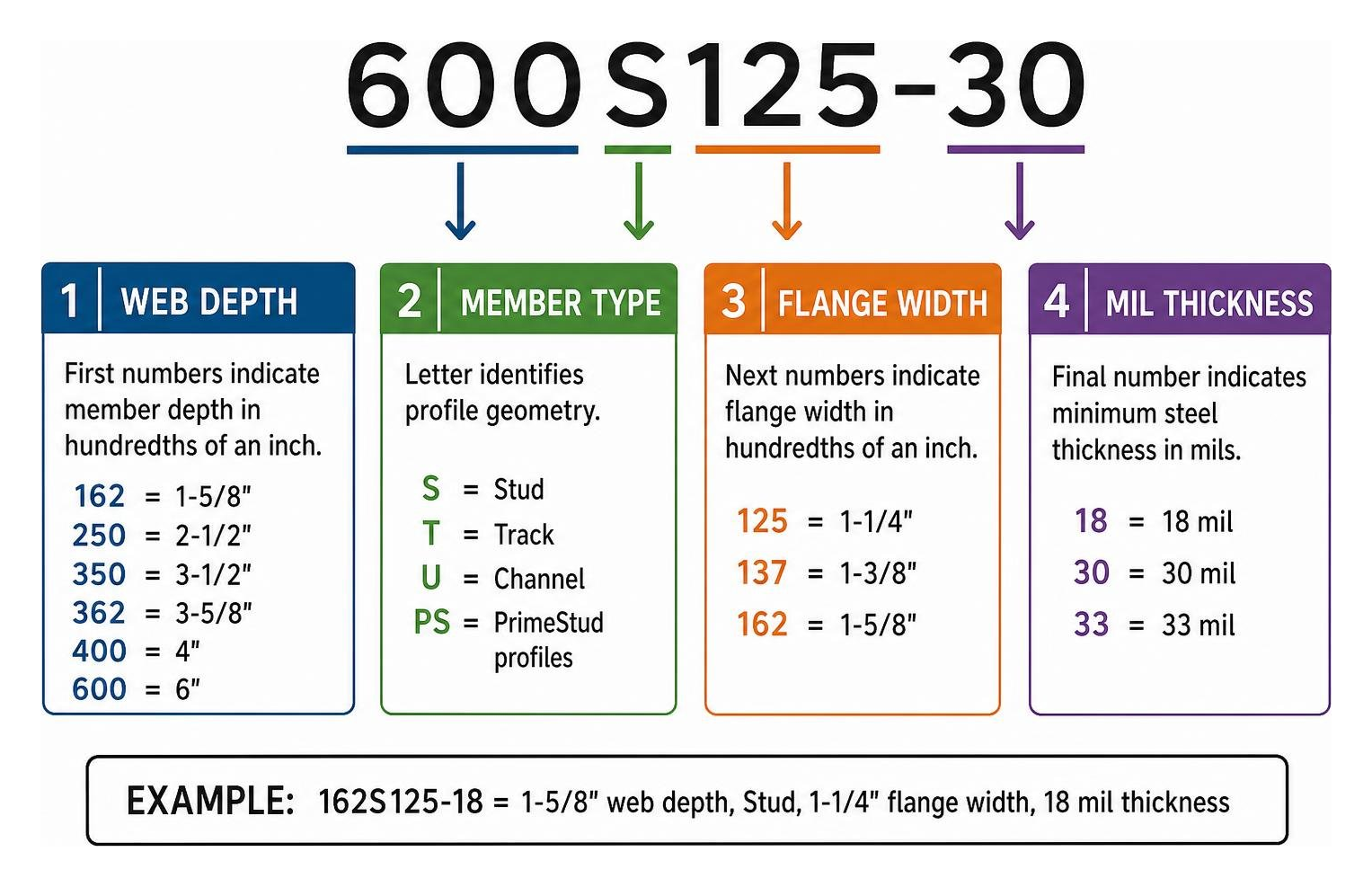
A typical designation looks like 600S125-30 or 162S125-18:
- Web Depth: The first numbers represent the member depth in hundredths of an inch. A
162indicates a 1-5/8″ web,250indicates 2-1/2″,350indicates 3-1/2″,362indicates 3-5/8″,400indicates 4″, and600indicates a full 6″ web. - Member Type: The letter identifies the profile geometry (
Sfor Stud,Tfor Track,Ufor Channel, andPSfor PrimeStud profiles). - Flange Width: The next numbers show the flange dimension in hundredths of an inch (
125= 1-1/4″,137= 1-3/8″,162= 1-5/8″). - Mil Thickness: The final number specifies minimum steel thickness in mils (
18= 18 mil,30= 30 mil,33= 33 mil).
For example, a 250PS137-24 indicates a 2-1/2″ PrimeStud profile with a 1-3/8″ flange and 24 mil thickness, whereas a 600S125-30 specifies a 6″ drywall stud with 1-1/4″ flanges and 30 mil steel.
Mil Thickness, Gauge, and Design Thickness
Historically, the construction trade relied on legacy sheet metal gauges. In modern engineering, gauges are imprecise because manufacturing allowances can create wide variations in structural capacity. Today, specifications rely strictly on decimal design thickness and mil thickness (1 mil = 0.001 inches).
When comparing galvanized steel studs, building codes require framing members to deliver a delivered base metal thickness of at least 95% of the design thickness. A traditional 25-gauge drywall stud has a design thickness of 0.0188 inches (18 mil), while a heavy 20-gauge structural framing stud has a design thickness of 0.0346 inches (33 mil).
| Legacy Gauge Designation | Mil Thickness (mils) | Design Thickness (in) | Minimum Thickness (95% Rule) (in) | Typical Weight (lbs/ft for 2-1/2″ Web) | Structural Classification |
|---|---|---|---|---|---|
| 25 GA Drywall (EQ) | 15–18 mil | 0.0158–0.0188 | 0.0147–0.0179 | 0.352–0.397 | Non-Structural Partition |
| 20 GA Drywall (DW) | 18–24 mil | 0.0188–0.0248 | 0.0179–0.0236 | 0.415–0.520 | Heavy Non-Structural |
| 20 GA Structural (STR) | 30–33 mil | 0.0312–0.0346 | 0.0296–0.0329 | 0.612–0.680 | Structural / Load-Bearing |
| 18 GA Structural | 43 mil | 0.0451 | 0.0428 | 0.875 | Structural / Curtain Wall |
| 16 GA Structural | 54 mil | 0.0566 | 0.0538 | 1.085 | Heavy Structural Framing |
| 14 GA Structural | 68 mil | 0.0713 | 0.0677 | 1.350 | Heavy Structural Framing |
| 12 GA Structural | 97 mil | 0.1017 | 0.0966 | 1.885 | Maximum Structural Framing |
Mechanical Properties and Structural Design Standards
Specifying the correct framing profile requires understanding how cross-sectional geometry handles applied forces. Engineers evaluate both gross sectional properties (the entire theoretical steel shape) and effective sectional properties (which discount thin steel areas prone to local buckling under compression).
Engineering Calculations in Metal Studs Specifications
When reviewing a manufacturer’s product specification sheet, look at these fundamental structural parameters:
- Moment of Inertia (Ixe): Quantifies resistance to bending deflection along the strong axis. A 6″ 20-gauge drywall stud (600S125-30) delivers an Ix of approximately 2.23 inches to the fourth power, whereas a 2-1/2″ 25-gauge stud provides an Ix of roughly 0.097 inches to the fourth power.
- Section Modulus (Sxe): Governs maximum bending stress capacity before steel reaches yield. The allowable bending moment (Ma) directly derives from multiplying Sxe by the allowable steel stress. For instance, an 18 mil 6″ high-strength stud can achieve an allowable bending moment (Ma) of 5,891 in-lbs and an allowable shear force (Va) of 104 lbs.
- Radius of Gyration (rx, ry): Measures column stability and resistance to axial buckling relative to member length.
Yield Strength, Web Stiffeners, and Torsional Bracing
Steel yield strength (Fy) indicates the maximum stress steel withstands before permanent deformation occurs. Standard framing studs are formed from 33 ksi, 40 ksi, 41 ksi, or ultra-high-strength 70 ksi cold-rolled sheet steel. Steels with higher yield strengths (like 70 ksi) allow thinner base metals to achieve substantial bending moments.
However, deep studs with ultra-thin walls create high web-height-to-thickness ratios (h/t). When the web-to-thickness ratio exceeds 200 (or 260 in certain proprietary assemblies), the steel web can buckle locally under concentrated reactions at track connections. To prevent web crippling, engineers specify track bearing stiffeners or specialized solid web clips at connection points.
Cold-formed steel studs also require lateral and torsional restraint. Because C-shaped channels have an open cross-section where the shear center sits outside the web, unbraced studs tend to twist when subjected to bending. The St. Venant torsional constant (J) and warping constant (Cw) determine a member’s resistance to lateral torsional buckling. Without continuous sheath bracing or mechanical CRC lateral bridging channels running through the web punchouts, an unbraced stud’s allowable bending capacity drops sharply.
Determining Limiting Heights and Deflection Criteria
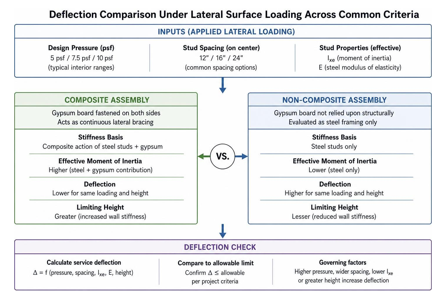
Wall heights are governed by applied lateral surface pressure, on-center stud spacing, and the allowable deflection limit. In standard commercial interiors, typical design pressure differentials range between 5 psf (pounds per square foot), 7.5 psf, and 10 psf.
When mastering partition wall framing techniques, selecting the correct spacing (12″, 16″, or 24″ on center) allows you to balance material costs while staying well within code-mandated deflection envelopes.
Composite vs. Non-Composite Wall Assemblies
A central decision in cold-formed steel engineering is whether to design a partition as a composite or non-composite assembly:
- Full Composite Assembly: Assumes gypsum drywall panels are securely fastened along both flanges from floor to ceiling. The gypsum board acts as continuous lateral bracing and forms a structural diaphragm with the steel, increasing wall stiffness and limiting heights.
- Non-Composite Assembly: Evaluates the steel stud framing independently. Gypsum board is considered dead load rather than a structural stiffener. Non-composite designs are mandatory for walls with open plenums, chase walls, walls paneled on only one side, or partitions utilizing vertical deflection tracks at the ceiling deck.
| Stud Member Designation | Spacing (O.C.) | Assembly Action Type | Max Height (L/120) @ 5 psf | Max Height (L/240) @ 5 psf | Max Height (L/360) @ 5 psf |
|---|---|---|---|---|---|
| 250S125-18 (25 GA Std) | 16″ O.C. | Composite (1/2″ Gypsum) | 12′-7″ | 10′-0″ | 8′-8″ |
| 250S125-18 (25 GA Std) | 16″ O.C. | Non-Composite (Braced) | 10′-5″ | 8′-3″ | 7′-2″ |
| 250PS137-24 (PrimeStud) | 16″ O.C. | Non-Composite (Braced) | 14′-1″ | 11′-2″ | 9′-9″ |
| 250USTE (20 GA DW-EQ) | 16″ O.C. | Composite (1/2″ Gypsum) | 16′-5″ | 13′-0″ | 11′-4″ |
| 600S125-18 (20 GA EQ-70ksi) | 16″ O.C. | Full Composite (5/8″ Type X) | 29′-10″ | 23′-8″ | 20′-8″ |
| 600S125-18 (20 GA EQ-70ksi) | 16″ O.C. | Non-Composite (Braced) | 23′-3″ | 18′-9″ | 16′-4″ |
| 600S125-30 (20 GA STR) | 16″ O.C. | Non-Composite (Braced) | 30′-6″ | 24′-2″ | 21′-1″ |
Deflection Limits and Gypsum Fastening with Grabber Fasteners
Deflection represents the allowable horizontal bow of a wall under lateral wind or interior air pressure:
- L/120: Standard utility partitions, storage rooms, and temporary assemblies. Deflection equals wall height divided by 120.
- L/240: Standard commercial office and residential partitions finished with 1/2″ or 5/8″ drywall panels.
- L/360: High-end interior finishes, moisture-resistant assemblies, Durock cement board backer installations, and walls finished with brittle ceramic tile or stone masonry to prevent grout cracking.
Fastener selection directly impacts composite strength. When selecting drywall dimensions and panel thickness, pair your board with premium Grabber drywall screws to prevent fastener pop-outs and preserve diaphragm rigidity.
For light-gauge drywall studs (18–24 mil), use standard Grabber bugle-head sharp-point screws. For heavy structural studs (33 mil and thicker), switch to Grabber self-drilling TEK-point fasteners to penetrate structural steel without stripping or mushrooming the sheet metal. For heavy warehouse and commercial shell partitions, pairing rigid steel studs with proper warehouse insulation packages (such as R-30+ in drop ceilings and R-13+ within stud cavities) maximizes building thermal performance.
Follow ASTM C754 screw spacing schedules: space screws a maximum of 16″ on center along the stud when framing is placed at 12″ or 16″ intervals, and reduce screw spacing to 12″ on center when studs are spaced at 24″ intervals.
Advanced Framing Features and Code Compliance
Modern steel framing systems incorporate engineered geometries that boost installation speed, utility integration, and structural deflection compliance.
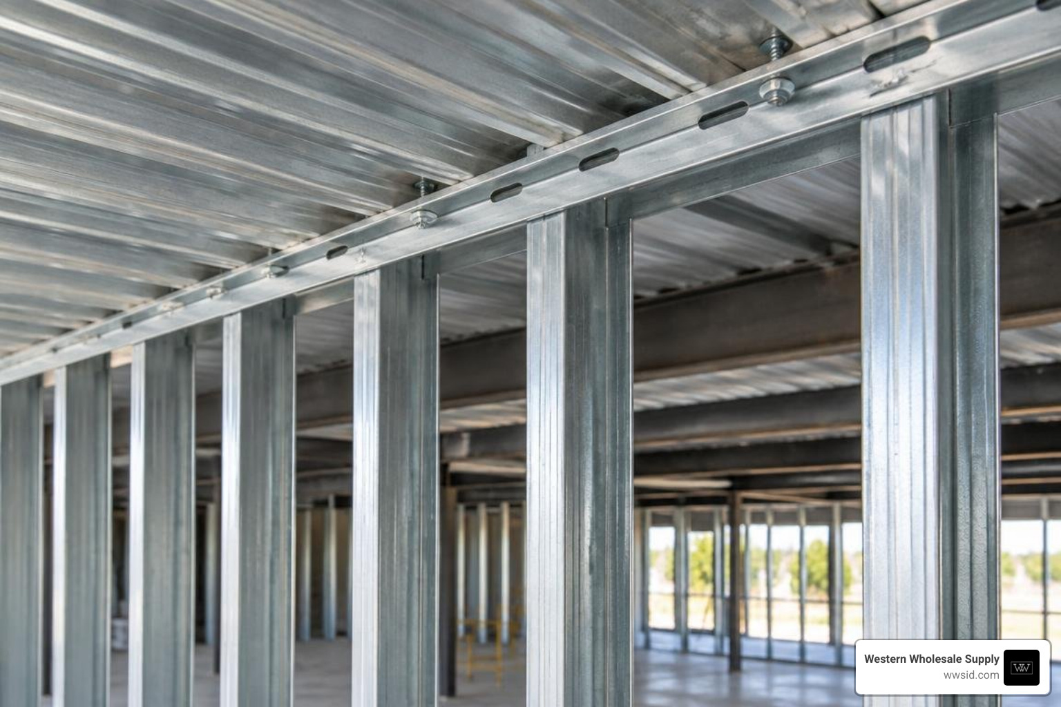
Proprietary Profiles and Knockout Alignments in Metal Studs Specifications
Framing manufacturers use cold-working processes to improve stiffness without increasing steel weight. Patented dimpled designs cold-work sheet steel across the entire profile surface, raising base yield strength up to 40 ksi and producing an effective composite thickness greater than smooth steel sheet.
Standard drywall studs also feature pre-punched service knockouts spaced along the centerline of the web (typically starting 12 inches from the member base and repeating at 24-inch intervals). These factory punchouts allow mechanical, plumbing, and electrical lines to route cleanly through partitions. Always install plastic snap-in grommets into raw steel punchouts to protect copper piping and electrical conduit insulation from vibration wear.
Where partitions meet floor slabs or roof decks above, install slotted head-of-wall deflection tracks. These deep-leg tracks feature vertical slots along the flange. Fastening Grabber screws through the center of the vertical slot into the stud top provides lateral wall stability while accommodating up to 1-1/2 inches of live-load structural slab deflection without crushing the studs or cracking finished drywall.
ASTM and IBC Building Code Standards
To satisfy regional and local municipal requirements—such as Idaho municipal design and construction standards across Eastern Idaho and Western Wyoming—framing products must comply with industry standards:
- ASTM C645: Standard Specification for Non-Structural Steel Framing Members.
- ASTM A653 / A653M: Standard Specification for Steel Sheet, Zinc-Coated (Galvanized) with minimum G40 (standard interior) or G60 (enhanced moisture) protective coatings.
- ASTM C754: Standard Specification for Installation of Steel Framing Members to Receive Screw-Attached Gypsum Panel Products.
- AISI S100-16 / S220: North American Specifications for the Design of Cold-Formed Steel Structural Members.
- UL 263 / ASTM E119: Fire Tests of Building Construction and Materials, verifying hourly fire ratings (such as 1-hour and 2-hour partitions using 5/8″ Type X gypsum or Quietrock EZ Snap acoustic drywall).
Frequently Asked Questions About Metal Stud Specifications
What is the difference between mil thickness and gauge in metal studs?
Mil thickness measures exact physical steel thickness in thousandths of an inch (1 mil = 0.001″), while legacy gauge numbers represent approximate thickness classifications. Because different manufacturers historically formed studs from varied sheet tolerances, building codes require specifications to state mil thickness and decimal base metal thickness. Under modern AISI guidelines, the delivered base steel thickness must never fall below 95% of the specified design thickness.
When are web stiffeners required on deep metal studs?
Web stiffeners are required whenever a stud’s web-height-to-thickness ratio ($h/t$) exceeds 200 (or 260 for certified proprietary profiles), or where concentrated bearing reactions exceed the member’s web crippling capacity. On deep web profiles (such as 6″ drywall studs with 18 mil thickness), solid steel track pieces, heavy-gauge stud scraps, or engineered web reinforcement clips must be fastened at bearing track connections to transfer vertical and lateral loads without crushing the web.
How does drywall screw spacing affect composite limiting heights?
Drywall screw spacing dictates how effectively gypsum wallboard and steel framing work together as a unit. Under ASTM C754, fastening Grabber screws at 12″ to 16″ intervals creates a rigid diaphragm that braces the stud flanges against lateral torsional twisting. If screw spacing is widened beyond code maximums, or if drywall is attached to only one side of the partition, the assembly loses composite action, lowering maximum wall height to non-composite limits.
Conclusion
Selecting the right cold-formed steel framing involves checking web depth, mil thickness, yield strength, and deflection limits. By matching certified metal studs specifications with Grabber fasteners and tested gypsum assemblies, you guarantee long-lasting, code-compliant partitions.
For complete engineering data and product guidance, explore our Steel Studs Survival Guide by Western Wholesale Supply. As a veteran-owned, third-generation family business serving Eastern Idaho and Western Wyoming since 1963, Western Wholesale Supply delivers reliable building materials—from steel framing and CertainTeed ceiling systems to Durock cement board, Hyde and Marshalltown drywall tools, and Brighton Best fasteners—straight to your jobsite.
